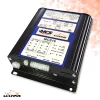

Universal CAN BUS Module MCS 32 is a simple solution for all firefigting, police and emergency vehicle upgraders.
Features:
- Quick installation – integrated and adjustable functions reduce installation time by up to 50%
- No relays and no fuses – completely removing standard relays and fuses increases the reliability of your electrical installations
- Automatic standby – the product is equipped with an automatic “standby” function that can be controlled with a vehicle key or CAN-BUS communication with the vehicle
- Multi-voltage – MCS products run on 12V and 24V
- Turn all required functions on or off using one key
- Power management – battery monitoring and adjustable charging monitoring Secondary battery activation control
- Heating and cooling control – available integrated interface that allows heating and cooling control directly from the console
Technical specifications for Universal CAN BUS Module MCS 32:
| OUTPUTS | 32 |
| HI POWER OUTPUTS | 20 Amps per channel
Current limiting Multi flash patterns Timer shutdown Voltage drop out |
| LO POWER OUTPUTS (12) | 600mA per channel
Positive or Negative switching Provide monitoring signal inputs (not high impedence) Negative polarity to switch low power relays |
| MEDIUM POWER OUTPUTS (4) | 2.5 Amps per channel
Positive or Negative switching Drive relays Small motors Monitor outputs |
| DIODE PAIRS BUILT IN FOR HEADLIGHT AND/OR TAIL LIGHT FLASHERS | |
| OUTPUT TO DATA LOGGER | |
| ELECTRIC FUSES | Electronically adjustable
Electronically tripped |
| INPUTS | 24 Configurable Inputs
12 negative switching 12 positive switching |
| STANDARD INPUTS (4) | Mic input
Radio input Reset Standby |
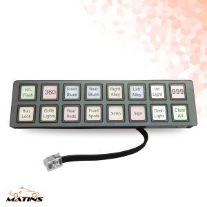
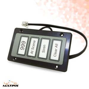
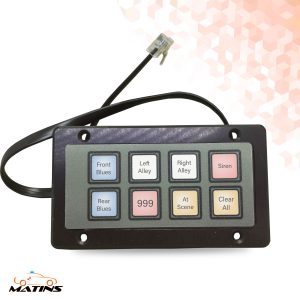
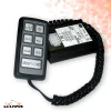
| MULTY-WAY SWITCH OPTIONS | Universal multi-way handset can be fully configured using the MCS software
Single or up to 4 handsets |
| SERIAL DATA PORT | RS485 protocol
RS232 via adaptor Link with third party MDT terminals USB input |
| CAN OR CAN TYPE DATA PORT | Link to MATINS complementary devices
Link to other industry new standard devices via CAN BUS Link with legacy equipment |
| USER INTERFACE
|
24 illuminated status indicators
Indicates flash pattern Communication status Provides output status Green – OK Red – over current Amber – low voltage |
| SPECIFICATION | 12/24 operating voltage
100 A current Approval to specification 5 e-approval |
The configuration software can be downloaded here.
Other control modules in our offer can be browsed here.
*The product may differ from image.